Hydraulic Calculator
Metric / Inch • Cylinder • Motor • Pump • Converter • Orifice Drop • PipingForce, speed, time and volume (extend / retract)
Key relations: F = P × A and v = Q ÷ A. Results update as you type.
Includes area ratio and return flow
Need a fast hydraulic check without digging through manuals? Use this calculator to plug in your flow, pressure, displacement, efficiency, pipe size, and fluid data and get clear, instant results—motor torque/speed/power, cylinder force and cycle time, pump flow and shaft power, quick unit conversions, orifice pressure drop, and piping velocity with Reynolds number. You can flip between Metric and Inch units anytime, watch the numbers update live as you type, and use the “calculate one value” dropdowns plus reset buttons to solve exactly what you’re missing in seconds.
What this tool calculates
This calculator is organized into six modules:
- Cylinder: force, speed, time, volume, return flow
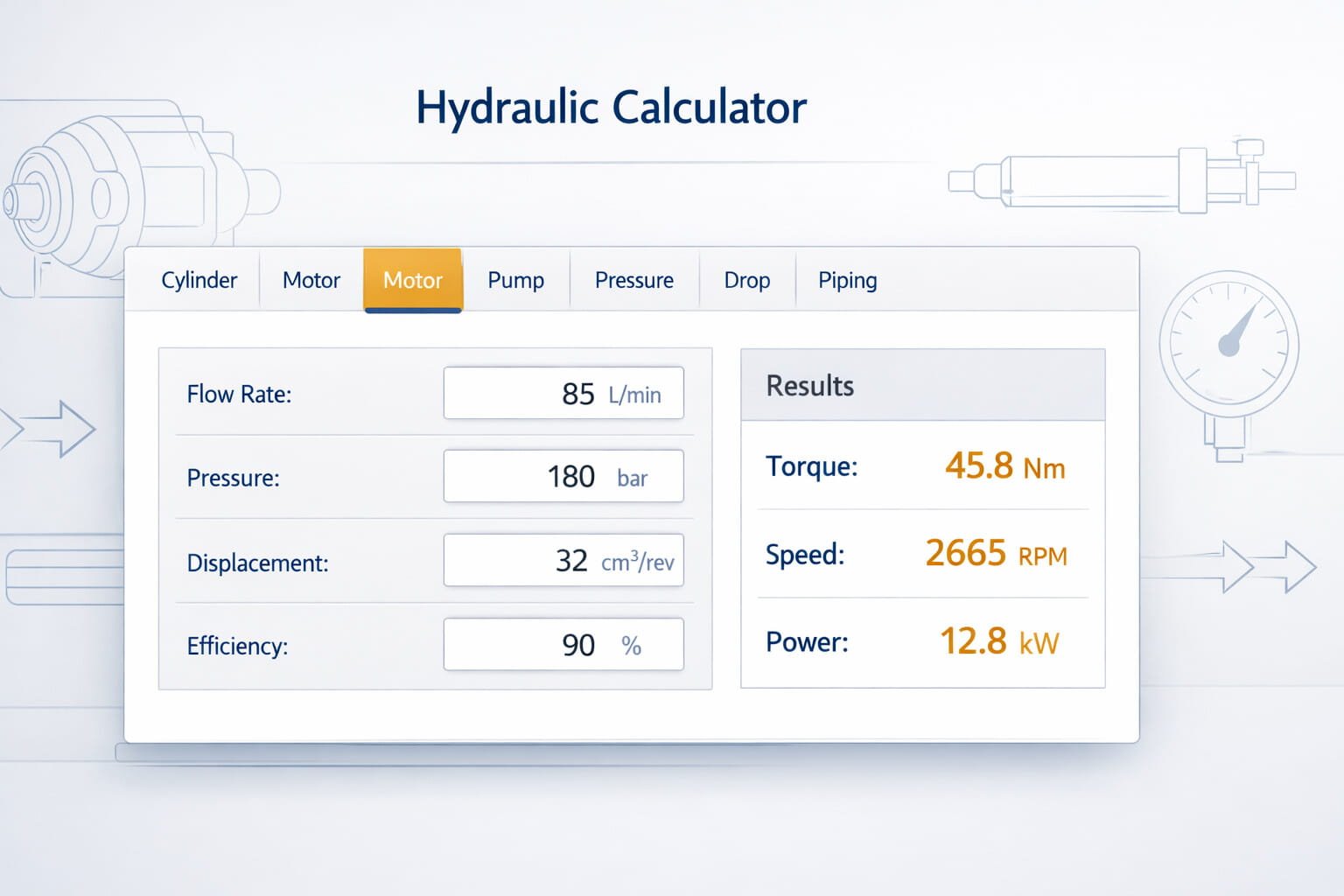
- Motor: solve for flow, pressure, displacement, speed, torque, or power
- Pump: solve for flow, displacement, shaft power, or total efficiency
- Pressure: unit conversion and hydraulic power calculations
- Drop (Orifice): estimate pressure drop across an orifice plate (or estimate flow from ΔP)
- Piping: velocity and Reynolds number using dynamic or kinematic viscosity
Each module is designed to be practical and quick, while still showing the values you typically need for system sizing and sanity checks.
How to use the calculator
- Choose your unit system: Metric or Inch
- Select a module tab: Cylinder, Motor, Pump, Pressure, Drop, or Piping
- Enter known values in the input fields
- The calculator updates results and shows outputs in the selected units
- Change units from dropdowns when you need to match project requirements
Tip: When troubleshooting, enter the measured field values first (pressure, flow, speed). Then compare the calculated results with the expected machine behavior.
Quick Reference Table (Modules and outputs)
| Module | Typical inputs | Key outputs |
|---|---|---|
| Cylinder | Bore, rod, stroke, pressure, flow | Force, speed, time, areas, volumes, return flow, area ratio |
| Motor | Flow, pressure, displacement, speed, efficiencies | Solve one of: flow, pressure, displacement, speed, torque, power |
| Pump | Pressure, speed, displacement or flow, efficiencies | Flow, displacement, shaft power, total efficiency |
| Pressure | Pressure and flow or conversion values | Converted units, hydraulic power |
| Drop (Orifice) | Cd, density, pipe diameter, orifice diameter, flow or ΔP | Pressure drop or flow rate, beta ratio, velocity |
| Piping | Flow, pipe ID, density, viscosity | Velocity, Reynolds number, flow regime |
Cylinder Calculator
What it’s for
Cylinder calculations are used for:
- selecting bore and rod size
- estimating push and pull force
- checking speed and cycle time
- understanding differential flow between extend and retract
What you enter
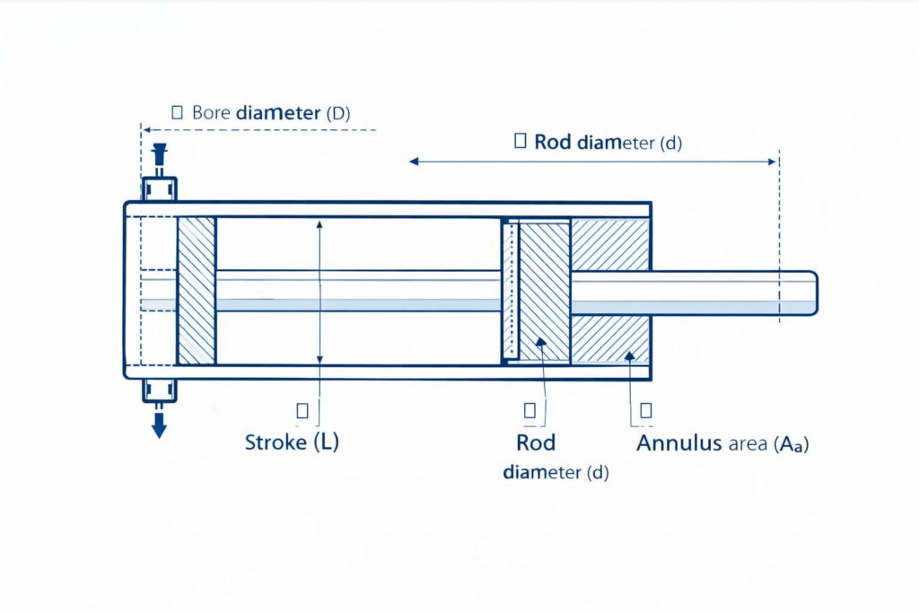
- Bore diameter (piston diameter)
- Rod diameter
- Stroke length
- Pressure
- Flow rate supplied to the active chamber
What you get
- Bore-side and annulus-side effective areas
- Extend force and retract force
- Extend speed and retract speed
- Extend time and retract time
- Chamber volumes and estimated return flow
- Area ratio (useful for differential cylinder behavior)
Practical notes
- Extend force is higher than retract force (rod reduces effective area on the retract side).
- Extend speed is usually lower than retract speed for the same flow (because retract area is smaller).
- Real systems experience friction and line losses. Use this as an engineering estimate.
Areas
- Bore area: \(A_b=\frac{\pi D^2}{4}\)
- Rod area: \(A_r=\frac{\pi d^2}{4}\)
- Annulus area: \(A_a=A_b-A_r\)
Force
- General: \(F=P\cdot A\)
- Extend: \(F_{ext}=P\,A_b\)
- Retract: \(F_{ret}=P\,A_a\)
Speed & Time
- Speed: \(v=\frac{Q}{A}\)
- Extend: \(v_{ext}=\frac{Q}{A_b}\), Retract: \(v_{ret}=\frac{Q}{A_a}\)
- Time: \(t=\frac{L}{v}\)
Volume & Return Flow
- Volume: \(V=A\cdot L\)
- Bore-side: \(V_b=A_b L\), Rod-side: \(V_a=A_a L\)
- Return flow (approx): \(Q_{return}=v\cdot A_{other}\)
- Extend: \(Q_{ret,ext}=v_{ext}A_a\), Retract: \(Q_{ret,ret}=v_{ret}A_b\)
Area Ratio
- \(\text{Ratio}=\frac{A_b}{A_a}\)
Motor Calculator
What it’s for
Hydraulic motors are typically sized by:
- required torque at a given pressure
- required speed for a given flow
- available power and efficiency
This module lets you choose what you want to calculate: flow rate, pressure, displacement, speed, torque, or power. The remaining fields are treated as inputs.
Recommended workflow (most common)
- If your priority is torque: set pressure and displacement, then calculate torque.
- If your priority is RPM: set flow and displacement, then calculate speed.
- If you know power and need pressure: set power and flow, then calculate pressure (with efficiency awareness).
Efficiency matters
Real motors are not ideal. Volumetric and mechanical efficiencies shift results, especially at low speeds, high pressures, and worn components. Use motor datasheets when available.
Speed / Flow / Displacement
- Speed: \(n=\frac{Q\,\eta_v}{D}\)
- Flow: \(Q=\frac{D\,n}{\eta_v}\)
- Displacement: \(D=\frac{Q\,\eta_v}{n}\)
Torque / Pressure
- Torque: \(T=\frac{\Delta P\,D\,\eta_m}{2\pi}\)
- Pressure: \(\Delta P=\frac{T\,2\pi}{D\,\eta_m}\)
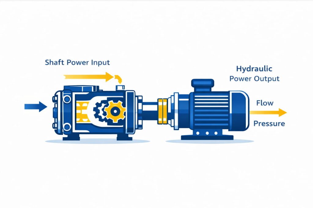
Power
- Mechanical output: \(P_{out}=T(2\pi n)\)
- Hydraulic input: \(P_{in}=\Delta P\cdot Q\)
Efficiency
- Total: \(\eta_t=\eta_v\eta_m\)
Pump Calculator
What it’s for
Pump calculations are essential for:
- selecting pump displacement to hit target flow at a certain RPM
- estimating shaft power needed at a given pressure and flow
- checking efficiency assumptions and heat risk
This module supports calculating:
- Flow rate
- Displacement
- Shaft power
- Total efficiency
Practical notes for pump sizing
- High pressure + high flow = high power demand. Ensure the prime mover (electric motor or engine) can supply it.
- If shaft power looks unusually high, re-check:
- pressure units (bar vs psi)
- flow units (L/min vs gpm)
- efficiency values
Flow / Displacement
- Flow delivered: \(Q=D\,n\,\eta_v\)
- Displacement: \(D=\frac{Q}{n\,\eta_v}\)
Power & Efficiency
- Hydraulic power (out): \(P_h=\Delta P\cdot Q\)
- Shaft power (in): \(P_{in}=\frac{\Delta P\cdot Q}{\eta_v\eta_m}\)
- Total efficiency: \(\eta_t=\frac{\Delta P\cdot Q}{P_{in}}\)
Pressure and Power
This section is designed for two common needs:
1) Unit conversion
Convert pressure, flow, power, and length between commonly used hydraulic units. This is helpful when:
- supplier datasheets are in imperial units
- your project is in metric
- you’re comparing components from different markets
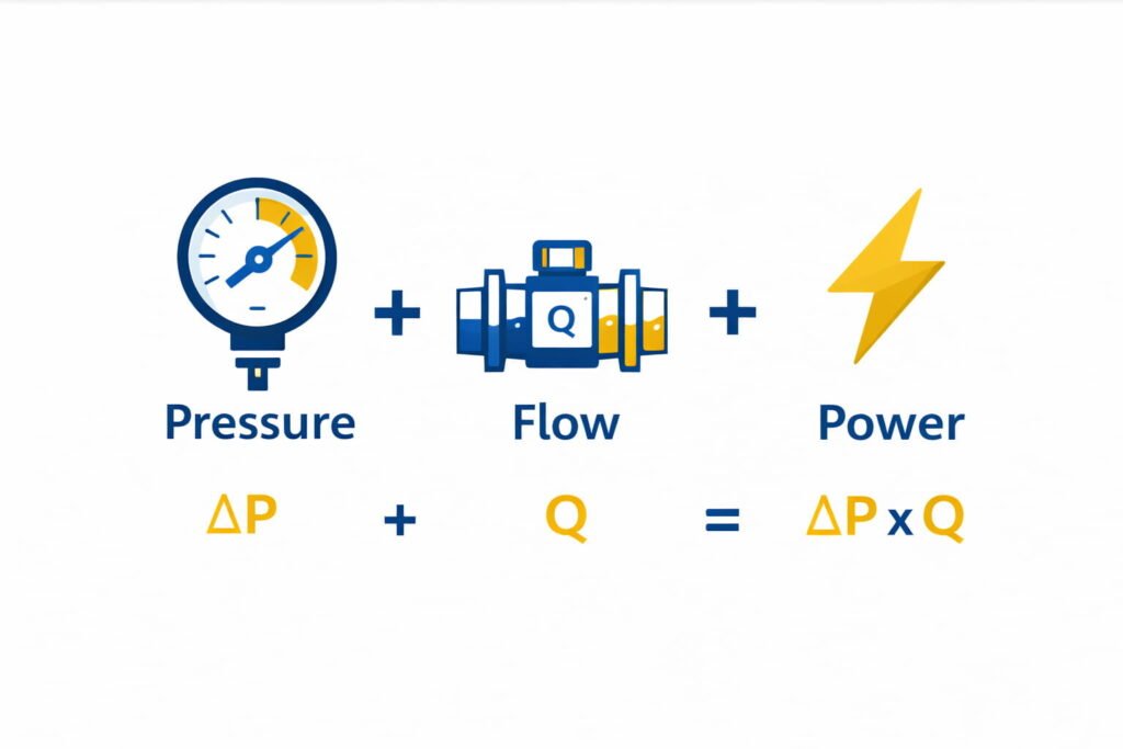
2) Hydraulic power (useful for sizing)
Hydraulic power is the product of pressure difference and flow rate. It helps you estimate:
- motor or pump power demand
- heat generation risk when efficiency is low
- whether a system is physically plausible
General Relation
- \(P=\Delta P\cdot Q\)
Industry Shortcuts (Ideal)
- \(P(\mathrm{kW})\approx\frac{\Delta P(\mathrm{bar})\cdot Q(\mathrm{L/min})}{600}\)
- \(P(\mathrm{hp})\approx\frac{\Delta P(\mathrm{psi})\cdot Q(\mathrm{gpm})}{1714}\)
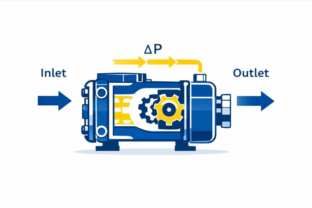
Drop (Orifice)
What it’s for
Orifice-style restrictions are common in:
- flow metering
- damping and snubbing
- simple throttling restrictions
- estimating losses across a plate or restriction
This module estimates either:
- Pressure drop (ΔP) from a known flow rate, or
- Flow rate (Q) from a known pressure drop
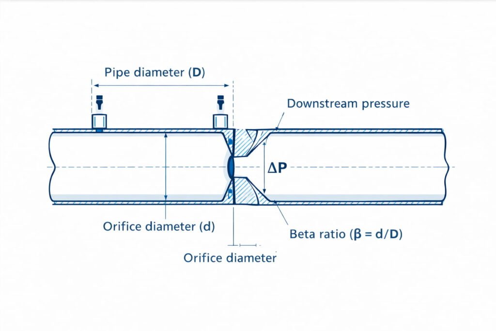
What the inputs mean (simple explanation)
- Cd: discharge coefficient (real-world correction factor)
- Density: fluid density affects the relationship between ΔP and flow
- Orifice diameter / Pipe diameter: geometry drives velocity and beta ratio
- Beta ratio: the orifice-to-pipe diameter ratio, which influences the correction term
Important: This is a useful estimate for liquids. For compressible flow (gases/steam), specialized standards and corrections are required.
Geometry
- Beta ratio: \(\beta=\frac{d}{D}\)
- Orifice area: \(A_2=\frac{\pi d^2}{4}\)
Flow / Pressure Drop
- \(Q=C_dA_2\sqrt{\frac{2\Delta P}{\rho(1-\beta^4)}}\)
- \(\Delta P=\frac{\rho(1-\beta^4)}{2}\left(\frac{Q}{C_dA_2}\right)^2\)
Velocity (Through Orifice)
- \(v=\frac{Q}{A_2}\)
Piping (Velocity and Reynolds Number)
Why it matters
Pipe sizing isn’t only about “will the oil pass through.” Velocity affects:
- pressure losses
- heat generation
- noise
- erosion risk (especially in tight restrictions and sharp bends)
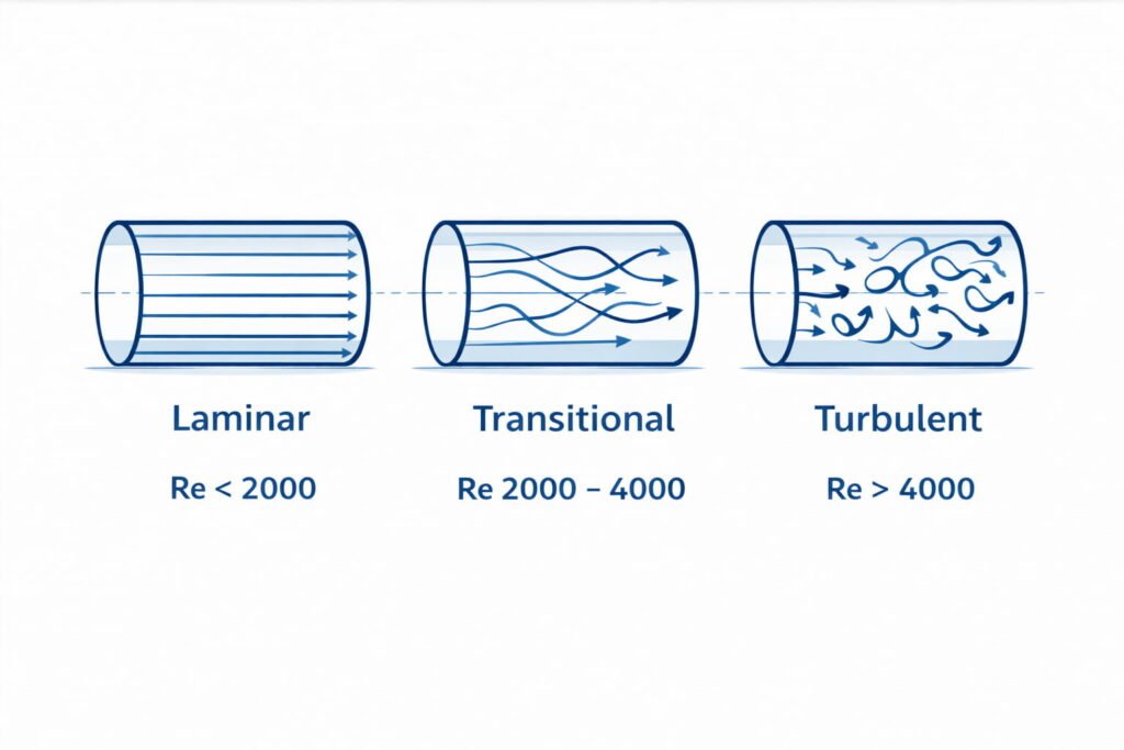
Reynolds number helps indicate flow regime:
- laminar
- transitional
- turbulent
This module calculates:
- cross-sectional area
- average velocity
- Reynolds number using either:
- Dynamic viscosity (μ), or
- Kinematic viscosity (ν)
Practical notes
- When oil is cold, viscosity is higher, which changes Reynolds number and losses.
- A system that works warm may feel sluggish cold due to viscosity effects.
Velocity
- Area: \(A=\frac{\pi D^2}{4}\)
- Velocity: \(v=\frac{Q}{A}\)
Reynolds Number
- Dynamic viscosity: \(\mathrm{Re}=\frac{\rho vD}{\mu}\)
- Kinematic viscosity: \(\mathrm{Re}=\frac{vD}{\nu}\)
Flow Regime (Rule of Thumb)
- \(\mathrm{Re}<2300\) → Laminar
- \(2300\le\mathrm{Re}\le 4000\) → Transition
- \(\mathrm{Re}>4000\) → Turbulent
Common unit reference
| Quantity | Common Metric units | Common Inch units |
|---|---|---|
| Pressure | bar, MPa | psi |
| Flow | L/min | gpm (US) |
| Length | mm, m | inch, ft |
| Power | kW | hp |
| Displacement | cm³/rev | in³/rev |
| Torque | N·m | lbf·in, lbf·ft |
“Hydraulic design is easier when pressure, flow, displacement, and efficiency are viewed together—because changing one almost always changes the others.”
Troubleshooting table
| Symptom | Likely cause | What to check in the calculator |
|---|---|---|
| Cylinder is slow | low flow, oversized cylinder, high losses | Cylinder speed vs flow; Piping velocity and Reynolds |
| Cylinder has low force | pressure too low, wrong area assumption, leakage | Cylinder force; verify bore vs rod side |
| Motor can’t reach RPM | low flow, large displacement, efficiency loss | Motor speed calculation; reduce displacement or increase flow |
| Motor torque is weak | low pressure, small displacement, mechanical losses | Motor torque calculation; check ΔP and ηm |
| Pump runs hot | low efficiency, excessive throttling, high loss | Pump shaft power vs hydraulic power; check ΔP and Q |
| Unexpected pressure drop | restriction or small line diameter | Orifice ΔP estimate; piping velocity and regime |
❓ Frequently Asked Questions
Clear answers, quick formulas, and practical tips for the Hydraulic Calculator
1What is the difference between Metric and Inch mode?⌄
Metric mode is built around common SI workshop units like bar, L/min, and millimeters, which keeps most sizing steps familiar.
Inch mode simply switches to psi, gpm, and inches—the physics doesn’t change, only the unit labels and conversions do.
Same physics (example)
\[F=P\cdot A\]2Is cylinder force the same on extend and retract?⌄
Extend force uses the full bore area, so it’s typically the maximum pushing force the cylinder can produce at a given pressure.
Retract force is lower because the rod takes away area on the rod side, reducing the effective piston area.
Areas and force
\[A_b=\frac{\pi D^2}{4},\;A_r=\frac{\pi d^2}{4},\;A_a=A_b-A_r\] \[F_{ext}=P\,A_b,\qquad F_{ret}=P\,A_a\]3Why does retract speed often look faster than extend speed?⌄
If the pump delivers the same flow, the cylinder will move faster whenever the effective area is smaller.
Because the retract side usually has the annulus area (bore minus rod), retract speed often comes out higher than extend.
Speed from flow
\[v=\frac{Q}{A}\qquad\Rightarrow\qquad v_{ext}=\frac{Q}{A_b},\;v_{ret}=\frac{Q}{A_a}\]4What do “volumetric” and “mechanical” efficiencies mean?⌄
Volumetric efficiency is mainly about leakage—how much of the theoretical flow actually becomes useful flow through the machine.
Mechanical efficiency reflects friction and mechanical losses, which reduce delivered torque and power compared to ideal values.
Motor relations with efficiency
\[n=\frac{Q\,\eta_v}{D}\qquad T=\frac{\Delta P\,D\,\eta_m}{2\pi}\qquad \eta_t=\eta_v\eta_m\]5What efficiency values should I use if I don’t have a datasheet?⌄
For quick early sizing, many engineers start with realistic “healthy system” assumptions and then tighten them using manufacturer data.
A common starting range is 0.85–0.90 for each efficiency, but always confirm for critical duty and safety decisions.
Practical starting point
\[\eta_v\approx0.85\text{–}0.90,\qquad \eta_m\approx0.85\text{–}0.90\]6Why does the pump calculator ask for shaft power?⌄
Shaft power is what your prime mover must supply to turn the pump, so it’s the number that matters for motor/engine selection.
It’s typically higher than hydraulic power because real pumps lose energy to leakage and friction before the fluid sees it.
Hydraulic vs shaft power
\[P_h=\Delta P\cdot Q\qquad P_{in}=\frac{\Delta P\cdot Q}{\eta_v\eta_m}\]7What is the “total efficiency” in the pump module?⌄
Total efficiency tells you how effectively input shaft power becomes useful hydraulic output at your chosen operating point.
It links the output power in the fluid to the input power at the shaft, combining leakage and mechanical losses together.
Total efficiency
\[\eta_t=\eta_v\eta_m=\frac{\Delta P\cdot Q}{P_{in}}\]8What does “displacement” mean for a motor or pump?⌄
Displacement is the volume moved per revolution, so it connects rotational speed to flow (pump) and pressure to torque (motor).
Higher displacement typically means more flow per RPM for pumps and more torque per bar/psi for motors (all else equal).
How displacement shows up
\[\text{Pump: }Q=D\,n\,\eta_v\qquad \text{Motor: }T=\frac{\Delta P\,D\,\eta_m}{2\pi}\]9What is Reynolds number in simple words?⌄
Reynolds number is a quick indicator of flow behavior—whether it tends to stay smooth or becomes mixed and turbulent.
It helps you judge trends in losses and stability, especially when viscosity or velocity changes in your hydraulic lines.
Reynolds number
\[\mathrm{Re}=\frac{\rho vD}{\mu}\quad\text{or}\quad \mathrm{Re}=\frac{vD}{\nu}\]10Why does viscosity matter so much in hydraulics?⌄
Viscosity changes with temperature, so the same system can behave very differently when cold-starting versus operating warm.
Higher viscosity can raise pressure losses and sluggish response, while very low viscosity can increase leakage in worn components.
Viscosity influences Re and losses
\[\mathrm{Re}=\frac{\rho vD}{\mu}\]11Can I use the Drop (Orifice) section for valves and fittings?⌄
You can use it as a rough “restriction-like” estimate, which is helpful for quick comparisons or early sizing checks.
For accurate valve/fitting results, you usually need manufacturer Kv/Cv data or tested loss coefficients for that component.
Orifice-style restriction model (liquid)
\[Q=C_dA_2\sqrt{\frac{2\Delta P}{\rho(1-\beta^4)}}\]12Is the calculator suitable for final design?⌄
This is a design-support tool—excellent for sizing, validation, and fast “does this make sense?” engineering checks.
Final design should still include full line losses, duty cycle/heat balance, real efficiency curves, safety factors, and applicable standards.
Fast sanity check
\[P=\Delta P\cdot Q\]13Why do my calculated numbers differ from field measurements?⌄
Small differences are common because the measured pressure or flow point may not match the true component \(\Delta P\) and actual delivered flow.
Temperature, aeration, meter accuracy, leakage, relief valve behavior, dirty filters, and undersized lines can all shift real results.
Most disagreements come from “real” \(\Delta P\)
\[P=\Delta P\cdot Q\]14What fluid density should I use?⌄
If you don’t have the exact number, use a reasonable estimate for your hydraulic oil and confirm it later from the oil datasheet.
Density changes with temperature, but usually not as dramatically as viscosity—still, it matters in orifice/flow-drop calculations.
Density appears in the orifice model
\[Q=C_dA_2\sqrt{\frac{2\Delta P}{\rho(1-\beta^4)}}\]15How should I validate the results quickly?⌄
Start with practical checks: does cylinder force cover the load, is motor power within prime-mover limits, and is piping velocity reasonable?
Then do a consistency check—pressure, flow, and power should agree together; if one looks off, re-check units and measurement points.
Quick consistency check
\[P=\Delta P\cdot Q\]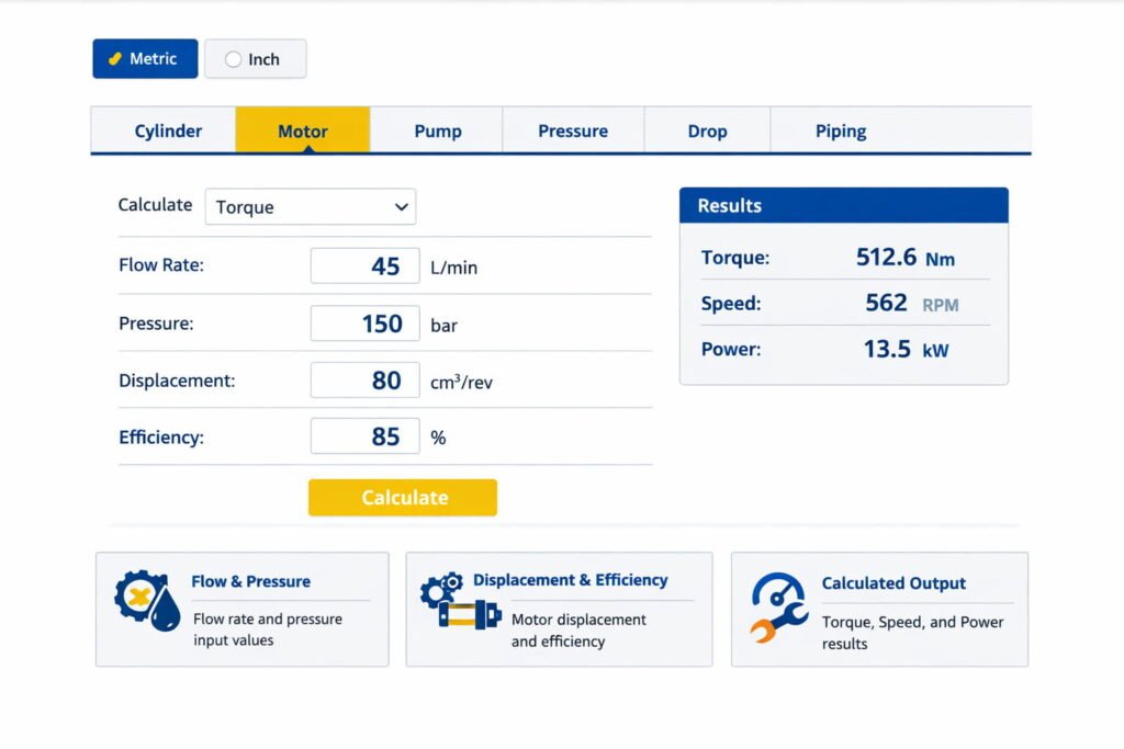
Safety and disclaimer
This calculator provides engineering estimates using standard hydraulic relationships. Real hydraulic systems are affected by temperature, viscosity changes, internal leakage, friction, fittings, hose expansion, filter condition, and component manufacturing tolerances. For safety-critical applications, verify results using manufacturer datasheets, applicable codes/standards, and qualified engineering review.